

The OSI model (Open Systems Interconnection model) is a multilayered reference model that shows how computer systems and applications communicate over a network. This seven-layer model provides a visual design of how each communications layer is built on top of the other, starting with the physical cabling, all the way to the application that’s trying to communicate with other devices on a network.
In doing so, this reference model provides a standard way for different systems and technologies to effectively communicate and interoperate. It also provides a clear structure for data transmission, and the model helps to manage and troubleshoot network issues.
Importance of the OSI model
A reference model is a conceptual framework for understanding relationships. It shows the relationships between the various elements of a network and offers a clear framework for describing the functions of a networking or telecommunications system that’s in use.
The purpose of the OSI reference model is to guide technology vendors and developers so the digital communications products and software programs that they create can interoperate. Most vendors involved in telecommunications try to describe their products and services in relation to the OSI model. This helps them differentiate among the various transport protocols, addressing schemes and communications packaging methods.
Additionally, the model provides a universally understood language for computer networking and communications. For this reason, IT networking professionals use it to conceptualize how data is sent or received over a network.
Anyone pursuing an IT networking certification should understand the OSI model as it is a foundational part of most certification programs, including Cisco Certified Network Associate and CompTIA Network+. The model is designed to break down data transmission standards, processes and protocols over a series of seven layers.
The OSI model is useful for guiding discussions around communications and evaluations of communications networks and their various elements. That said, the model is theoretical in nature and should be used only as a general guide. That’s because few network products or standard tools keep related functions together in well-defined layers like the OSI model. The TCP/IP suite, for example, is the most widely used network protocol, but even it doesn’t map cleanly to the OSI model.
How the OSI model works
The main concept of OSI is that the process of communication between two endpoints in a network can be divided into seven distinct groups of related functions, or layers. Each communicating user or program is on a device that can provide those seven layers of function.
In this architecture, each layer serves the layer above it and, in turn, is served by the layer below it. So, in a given message between users, there is a flow of data down through the layers in the source computer, across the network and then up through the layers in the receiving computer. Only the application layer at the top of the stack doesn’t provide services to a higher-level layer.
The seven layers of function are provided by a combination of applications, operating systems, network card device drivers, networking hardware and protocols that enable a system to transmit a signal over a network through various physical mediums, including twisted-pair copper, fiber optics, Wi-Fi or Long-Term Evolution with 5G.
7 layers of the OSI model
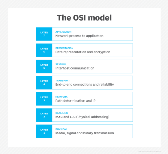
The OSI model consists of seven layers. Each layer has a unique function and specific responsibilities and directly interacts with the layer above it. The following are these seven layers from the highest to the lowest.
Layer 7. The application layer
The application layer is the human-to-computer interaction layer. It enables the user — human or software — to interact with the application or network whenever the user elects to read messages, transfer files or perform other network-related tasks.
This layer facilitates these interactions by providing the interface between user applications and underlying network services. This is where applications use various protocols and services to communicate with servers — and with each other — across the network. For example, web browsers use Layer 7 application protocols, like HTTP or File Transfer Protocol. Other internet-connected apps, like Outlook, use protocols such as Simple Mail Transfer Protocol (SMTP). When there is a need to resolve domain names to IP addresses, Domain Name System (DNS) is used.
Layer 6. The presentation layer
The presentation layer translates or formats data for the application layer based on the semantics or syntax the application accepts. This layer also handles the encryption and decryption that the application requires, ensuring that different systems can read the data sent by the applications of other systems.
Encryption is important to secure the data during transmission. The data may also be compressed in this layer. Compression helps ensure efficient data transmission by reducing its size without much affecting its integrity.
Layer 5. The session layer
The session layer controls the connections, or sessions, between computers and applications. It sets up, coordinates and terminates conversations to ensure efficient and organized data exchange.
The session layer synchronizes data transfers and determines how long a system waits for another application to respond. Its other services include authentication and reconnection after an interruption. It uses checkpoints that reduce the need to restart transfers in case of session interruptions. This enables sessions to resume post-interruptions with minimal data losses.
This layer uses specific protocols to manage and control sessions. Examples of such protocols are X.225 and Zone Information Protocol.
Layer 4. The transport layer
The transport layer sits in the middle of the OSI model and is responsible for transporting data between devices or applications in a network. It determines how much data to send, where it gets sent and at what rate. In addition, it breaks up the data received from the session layer into chunks called segments and controls the data between hosts to ensure efficient transmission. On the receiving end, the transport layer reassembles the segments into data that can then be consumed by the session layer.
The layer also provides error detection and correction mechanisms to ensure complete data transfers and facilitate effective recovery in case of errors.
TCP within the TCP/IP suite is the best-known example of a transport layer protocol. This protocol is commonly used for web browsing and email. This is where the communications select TCP port numbers to categorize and organize data transmissions across a network.
User Datagram Protocol (UDP) is also a transport layer protocol. Unlike TCP, UDP does not establish a handshake between the source and destination computers to enable them to communicate. For this reason, UDP is faster than TCP, making it suitable for broadcasts, time-sensitive applications and query-response protocols, like DNS. On the other hand, it is less reliable than TCP since it doesn’t require an end-to-end connection and does not include any data verification mechanisms.
Layer 3. The network layer
The primary function of the network layer is to move data into and through different networks. It receives segments from the transport layer and breaks them up into packets on the sender’s device. It then reassembles the packets on the receiving device.
Network layer protocols find the best physical path for data to move from the source to the destination. This is known as routing, a phenomenon that they accomplish by packaging data with correct network address information, selecting the appropriate network routes and forwarding the packaged data up the stack to the transport layer. From a TCP/IP perspective, this is where IP addresses are applied for routing purposes. Examples of network layer protocols include IP, Internet Control Message Protocol, Internet Group Management Protocol (IGMP) and Routing Information Protocol.
Layer 2. The data link layer
The data link layer, or protocol layer, handles moving data into and out of a physical link in a network. Layer 2 enables data transfers between devices on the same network. It facilitates these transfers by breaking down packets received from the network layer into smaller frames.
This layer also handles problems that occur as a result of bit transmission errors in intranetwork communication. It ensures that the pace of the data flow doesn’t overwhelm the sending and receiving devices. This layer also permits the transmission of data to Layer 3, where it gets addressed, routed and forwarded.
The data link layer can be further divided into two sublayers.
The higher layer, which is called logical link control, is responsible for multiplexing, flow control, acknowledgement and notification to upper layers if transmit/receive errors occur. The lower layer, known as the media access control sublayer, is responsible for tracking data frames using MAC addresses of the sending and receiving hardware. It’s also responsible for organizing each frame, marking the starting and ending bits, and organizing timing regarding when each frame can be sent along the physical layer medium.
Ethernet is one of the most commonly used technologies in the data link layer. It defines the rules for connections and data transmissions between the nodes in a network such as a local area network.
Layer 1. The physical layer
The physical layer transports data using electrical, mechanical or procedural interfaces, such as cables and switches. This layer is responsible for sending computer bits — strings of ones and zeros — from one device to another along the network through a physical medium.
The physical layer is important because it determines how physical connections to the network are set up. It also determines how the bits in a data bitstream are represented into predictable signals as they’re transmitted either electrically, optically or via radio waves (Wi-Fi).
Cross-layer functions of the OSI model
Some cross-layer functions or services may affect more than one layer in the OSI model. These include the following:
- Security service telecommunication as defined by the International Telecommunication Union Telecommunication Standardization Sector X.800 recommendation.
- Management functions that enable the configuration, instantiation, monitoring and terminating of the communications of two or more entities.
- Multiprotocol Label Switching, which operates at an OSI model layer that lies between the Layer 2 data link layer and the Layer 3 network layer — MPLS can carry a variety of traffic, including Ethernet frames and IP packets.
- Address Resolution Protocol translations of IPv4 addresses (OSI Layer 3) into Ethernet MAC addresses (OSI Layer 2).
- DNS, which is an application layer service that’s used to look up the IP address of a domain name.
How does data flow through the OSI model
During transmission, the OSI model determines how data flows from a sending device to a receiving device. In particular, the data from the sending device travels down the seven layers of the model, i.e., from the application layer (Layer 7) to the physical layer (Layer 1). It thens travel up the seven layers on the receiving end, i.e., from the physical layer to the application layer.
Suppose User A sends an email to User B. Here’s how data flows through the OSI model.
At the sending end
User A’s email client, e.g., Microsoft Outlook, sits on the application layer. It uses SMTP to pass the email message to the next layer, the presentation layer.
At the presentation layer, the email message gets compressed, encrypted and formatted. It is then passed on to the session layer.
At the session layer, a session is established between User A’s email server and User B’s email server. This connection remains open long enough to send the email from User A to User B.
Next, the data reaches the transport layer. Here, it is divided into smaller segments, which are sent on to the network layer. At the network layer, the segments are further divided into smaller packets, and each packet is assigned source and destination IP addresses to allow routing.
These packets travel to the data link layer, where they are further broken down into frames. The layer uses MAC addresses so the packets can move across local networks. Layer 2 also corrects any errors that occur as the data moves from Layer 7 to here.
Finally, the frames are delivered to the physical layer. Here, the data is converted into a bitstream of ones and zeros and sent through a physical medium, such as a fiber optic cable.
At the receiving end
The above process is reversed at the receiving end (User B).
First, the physical medium converts the received binary bitstream into frames that are passed to and reassembled into packets at the data link layer.
The data link layer passes the packets to the network layer, which checks that the packets have arrived correctly and also assembles them into larger segments.
These segments are passed to the transport layer. Here, the segments are reassembled or reordered as required.
The session layer maintains the session until User B fully receives the email from User A. It also passes on the reassembled email to the presentation layer. This layer decompresses, formats and decrypts the email, and it passes it on to the application layer.
Finally, the application layer delivers the email in human-readable format to User B’s email client — Outlook or something else. At this point, the email appears in User B’s inbox, and they can read it on a compatible device — desktop, laptop, tablet, smartphone, etc.
Pros and cons of the OSI model
The OSI model has a number of advantages, including the following:
- It’s considered a standard model in computer networking.
- The model supports connectionless, as well as connection-oriented, services. Users can take advantage of connectionless services when they need faster data transmissions over the internet and the connection-oriented model when they’re looking for reliability.
- It has the flexibility to adapt to many protocols. Different protocols can be used depending on the network’s requirements. For example, TCP can be used if reliable, error-free communication is required — say, for web browsing or email. Instead of TCP, UDP can be used if some reliability can be sacrificed in favor of faster communications for applications like online gaming or real-time video streaming.
- The model is more adaptable and enables the implementation of security applications and tools to enhance protection and resilience to cyberattacks.
The disadvantages of the OSI model include the following:
- It doesn’t define or recommend any particular protocol, so device manufacturers and vendors use their own judgment to determine which protocol should be used and when.
- The session layer, which is used for session management, and the presentation layer, which deals with user interaction, are less useful than the other layers in the OSI model.
- Some services are duplicated at various layers, such as the transport and data link layers, which can make it harder to understand the model.
- Layers cannot work in parallel; each layer must wait to receive data from the previous layer.
OSI model vs. TCP/IP model
The OSI reference model describes the functions of a telecommunications or networking system, while TCP/IP is a suite of communication protocols used to interconnect network devices on the internet. TCP/IP and OSI are the most broadly used networking models for communication.
The OSI and TCP/IP models have similarities and differences. The main similarity is in their construction, as both use layers, although the OSI model consists of seven layers, while TCP/IP consists of just four layers.
Another similarity is that the upper layer for each model is the application layer, which performs the same tasks in each model but may vary according to the information each receives.
The functions performed in each model are also similar because each uses a network and transport layer to operate. The OSI and TCP/IP models are mostly used to transmit data packets, although they each use different means and paths to reach their destinations.
Additional similarities between the OSI and TCP/IP models include the following:
- Both are logical models.
- Both define standards for networking.
- Both divide the network communication process in layers.
- Both provide frameworks for creating and implementing network standards and devices.
- Both enable one manufacturer to make devices and network components that can coexist and work with the devices and components made by other manufacturers.
- Both divide complex functions into simpler components.
The main difference between the OSI and TCP/IP models is that OSI is a conceptual and generic framework that describes network communication. In contrast, TCP/IP is a practical and functional model that helps to solve real communication problems and networking issues.
Other differences include the following:
- OSI uses three layers — application, presentation and session — to define the functionality of the upper layers. TCP/IP combines these layers into one application layer.
- For data transmission, OSI uses Layers 1, 2 and 3, while TCP/IP uses all its layers.
- OSI uses two separate layers — physical and data link — to define the functionality of the bottom layers, while TCP/IP uses only the link layer.
- OSI uses the network layer to define the routing standards and protocols, while TCP/IP uses the internet layer.
- OSI is a protocol-independent model, meaning it can be used to understand any kind of network. TCP/IP is based on specific, standard protocols that are widely used in internet networks.
History of the OSI model
In the 1970s, technology researchers began examining how computer systems could best communicate with each other. Over the next few years, several competing models were created and published to the community. However, it wasn’t until 1984 that the International Organization for Standardization (ISO) took the best parts of competing networking reference models to propose OSI as a way to finally create a framework that technology companies around the world could use as the basis of their networking technologies.
From ISO’s perspective, the easiest way to create a conceptual model was to organize the models into different abstraction layers required to organize and send data between computing systems. Looking inside each abstracted layer to see the details shows one part of this network communication process. Each layer can be thought of as a separate communication module or piece of the puzzle. But, to accomplish the goal of sending data from one device to another, each module must work together.
Networking is the backbone of the internet, and it relies on several essential protocols. These key network protocols are crucial for enabling seamless communication and connections across the internet.
